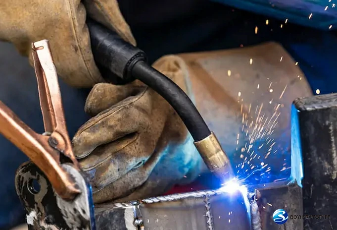
Welding is an essential joining technique that connects metal components of different shapes, sizes, and materials together. However, various defects may occur during the welding process due to lack of proficiency, unsuitable materials, or unfavorable environmental conditions. These defects can pose threats to the overall structural integrity and safety of the welded joints. Therefore, understanding common welding defects, analyzing their causes, and implementing appropriate remedial measures are of paramount importance for enhancing welding quality and ensuring product safety.
Structure of Welded Joint
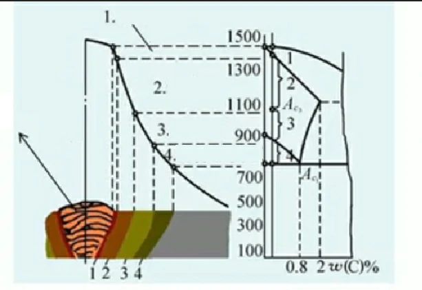
- Fusion Zone
- Coarse Grain Zone (Overheated Zone)
- Fine Grain Zone (Normalizing Zone or Phase Transformation Recrystallization Zone)
- Partial Phase Transformation Zone
Welding Defect Definition
In welding, the phenomenon of metal discontinuity, lack of density, or poor bonding within the welded joint is referred to as welding defects.
Types of welding defects:
- Some are caused by improper operation or incorrect welding parameters during welding, such as undercut, burn-through, bad welding, nsufficient weld size, lack of penetration, lack of fusion, etc.
- Some are caused by products of chemical metallurgy, solidification, or solid-state phase transformation processes, such as porosity, slag inclusion, cracks, etc.
What Are The Major Categories of Weld Imperfections?
Generally speaking, according to the nature of welding defects, they can be divided into three categories: shape and size defects, structural defects, and performance defects.
Shape and Size Defects:
Welding deformation, dimensional deviations (including misalignment, angular deviation, excessive or insufficient weld size), poor appearance (such as uneven weld height, rough ripples, inconsistent width), spatter, and arc strikes.
Structural Defects:
Surface porosity and internal porosity, inclusion of slag, lack of fusion, lack of penetration, weld bead, undercut, crater, and welding cracks.
Performance Defects:
Mechanical properties of welded joints (tensile strength, yield point, impact toughness, and cold bending angle), chemical composition, and other properties not meeting technical requirements.
Based on the internal and external locations of welding defects, they can be divided into: internal defects and external defects.
External Defects:
- Groove Defects
- External Defects of Weld Beads
- External Defects of Welded Joints (joint distortion and warpage)
Internal Defects:
- Internal Defects of Weld Beads and Welded Joints (porosity, cracks, lack of penetration, etc.)
- Poor Mechanical Properties of Welded Joints (failure to meet the mechanical properties and design requirements of the base material, mainly including: strength, plasticity, toughness, hardness)
- Poor Corrosion Resistance and Inappropriate Metallographic Structure of Weld Metal (changes in chemical composition of weld metal)
According to the causes of occurrence, welding defects can be categorized as:
- Defects Caused by Welding Equipment
- Defects Caused by Welding Materials
- Defects Caused by Welding Processes
18 Common Types of Welding Defects
Below, we will introduce 18 common welding defects, analyze their causes and effects, and provide reference for welding quality control.
- Undercut
- Incomplete fusion
- Incomplete penetration
- Cracks
- Slag inclusions
- Spatter
- Porosity
- Overlap
- Burn Through
- Underfill
- Misalignment
- Distortion
- Lamellar Tearing
- Mechanical damage
- Whiskers
- Inadequate reinforcement
- Too high weld current
- No preheat before starting welding
1.Undercut

Defect Description
The depression or groove appearing below the surface of the base metal along the weld toe (or weld root) due to welding is referred to as welding undercut.Undercut can occur on one or both sides of the weld joint and may be continuous or intermittent.
Hazard
Welding undercut reduces the effective cross-sectional area of the base material, lowers the load-bearing capacity of the structure, and also causes stress concentration, which develops into a crack source, further affecting the strength and stability of the welded part, and may even lead to the failure of the welded part.
Causes
- The current is too strong.
- The electrode is not suitable.
- The arc is too long, and the welding speed is too fast.
- Improper operation. When fillet welding, the electrode is not properly aligned.
- The base metal is not clean.
- The base metal is overheated.
- Poor weaving or handling during vertical welding, resulting in undercutting on both sides of the weld bead.
Remedies
- Use lower current.
- Select appropriate type and size of welding rod.
- Reduce arc length and speed.
- Adopt correct angle, slower speed, shorter arc, and narrower weave.
- For horizontal fillet welding, the position of the welding wire should be 1-2mm away from the intersection.
- Use welding rods with smaller diameter.
2.Incomplete Fusion

Defect Description
During fusion welding, the gap left between the weld metal and the base metal or between the layers of weld metal due to incomplete fusion is referred to as lack of fusion. There are three forms: lack of sidewall fusion, lack of inter-run fusion, and lack of root fusion.
Hazard
In the presence of impact loads, cyclic loads, or low-temperature operations, areas of incomplete fusion are prone to brittle fracture, leading to the failure of the entire welded structure.
Causes
- Welding current too low.
- Welding speed too fast.
- Incorrect angle of the electrode.
- Unreasonable groove design or processing.
- Incomplete cleaning of the weld area.
Remedies
- Using larger welding current.
- Controlling welding speed.
- Selecting appropriate electrode angle.
- Optimizing groove design and processing to avoid dead zones where liquid metal flow is hindered.
- Thoroughly cleaning the weld area and groove before welding to remove impurities such as oil, rust, etc.
3.Incomplete Penetration

Defect Description
During welding, the phenomenon where the root of the joint is not fully melted is referred to as incomplete penetration. In single-sided welding, when the fusion of the weld does not reach the root, it is called incomplete root penetration. In double-sided welding, incomplete penetration can also occur in the middle between the two welds.
Hazard
Causing a decrease in the strength of welded joints. Brittle fracture of welded structures.
Causes
- Improper selection of welding rods.
- Arc too small, welding speed too low.
- Welding speed too slow.
- Incorrect weld joint design and combination.
- Improper bevel angle.
Remedies
- Select welding rods with higher penetration.
- Reduce arc length, increase welding speed.
- Increase groove angle, increase gap to reduce root depth.
- Optimize bevel and gap design.
4.Cracks

Defect Description
Under the combined effects of welding stresses and other embrittling factors, during or after the welding process, the metal atomic bonding in localized regions (weld or heat-affected zone) of the welded joint is disrupted, resulting in the formation of new interfaces and gaps known as welding cracks.
Usually, according to the different mechanisms of crack generation, it can be divided into two categories: hot cracks and cold cracks.
Hot cracks
Hot cracks are generated during the crystallization process from liquid to solid in the weld metal, and most of them occur in the weld metal.
The main reason for its occurrence is the presence of low melting point substances (such as FeS, melting point 1193 ℃) in the weld seam, which weakens the connection between grains. When subjected to large welding stress, it is easy to cause fracture between grains.
When welding parts and welding rods contain impurities such as S and Cu, they are prone to thermal cracking.
Hot cracks have the characteristic of being distributed along grain boundaries. When the crack penetrates the surface and communicates with the outside world, it has a clear tendency for hydrogenation.
Cold cracks
Cold cracks are generated during the cooling process after welding, mostly at the fusion line between the base metal or the fusion line between the base metal and the weld seam.
The main reason for its occurrence is due to the formation of quenched microstructure in the heat affected zone or weld seam, which causes internal cracking of grains under high stress. When welding easily quenched steel with high carbon content or more alloying elements, cold cracks are more likely to occur.
Excessive hydrogen fusion into the weld can also cause cold cracks.

Hazard
Cracks are a very dangerous defect. In addition to reducing the load-bearing section, they can also cause serious stress concentration. During use, cracks will gradually expand, which may lead to component failure.
Causes
- Improper selection of welding materials.
- Excessive welding current, overly rapid welding speed, or excessively high welding temperature.
- Excessive density of weld joints, and unreasonable weld cross-sectional shape.
- Inadequate preheating before welding, and excessively rapid cooling after welding.
Remedies
- Avoid using materials with excessively high carbon content or excessive harmful impurities.
- Strictly control welding process parameters.
- Optimize welding structure design.
- After removing cracks, use appropriate welding materials and processes for repair welding.
- Conduct non-destructive testing of welded joints to promptly detect and repair any cracks and defects that may exist.
5.Slag inclusions

Defect Description
The slag trapped in the weld after welding is called slag inclusions.Slag inclusions are a type of macroscopic defect. They can take on various shapes such as circular, elliptical, or triangular, and are typically found at the junction of the weld bead and the base metal groove sidewall, or between adjacent weld beads. Inclusions can exist as individual particles or as elongated or continuous distributions in the form of strings or lines.
Hazard
Becoming the origin of cracks increases stress, leading to easy cracking of cold and hot brittleness, causing damage to components.
Causes
- Incomplete removal of slag from the previous layer.
- During multi-pass welding, the groove surface is affected by wire melting, and the wire is too close to the groove sidewall.
- Slag inclusion is prone to occur at the guide plate at the welding start point.
- Insufficient current, slow speed, excessive deposition.
- Excessive extension of the welding wire.
Remedies
- Thoroughly remove slag from the previous layer.
- Ensure the distance between the groove sidewall and the welding wire is at least greater than the diameter of the welding wire.
- The thickness of the guide plate and the shape of the groove should be the same as the base metal.
- Increase current and welding speed to facilitate slag removal.
- Follow the instructions for the use of various welding wires.
6.Spatter

Defect Description
Due to the effects of high temperature and electric arc, melted metal particles fly out of the melt pool, attach to the surface of the workpiece or splash into the surrounding environment.
Hazard
Spatter adheres to the surface of the weld bead, forming a discontinuous and uneven layer, which affects the appearance and performance of the weld. Metal particles from weld spatter may scatter within the work area, posing a safety threat to workers.
Causes
- Unstable welding parameters.
- Irregular groove forms.
- Surface defects on the welding wire.
- Large internal inclusions in the welding wire.
Remedies
- Ensure stable welding parameters.
- Ensure groove forms are regular and uniform.
- Use welding wires with smooth surfaces and minimal defects.
- Use high-quality welding wires with minimal internal inclusions.
7.Porosity

Defect Description
The voids formed by bubbles in the weld pool during solidification, which fail to escape in time and remain trapped, are called porosity.
Hazard
The presence of porosity primarily affects the integrity (gas tightness and water tightness) of the weld joint. Their presence not only weakens the effective cross-section of the weld but also introduces stress concentration, significantly reducing the strength and toughness of the weld metal. This is particularly detrimental to dynamic load strength and fatigue strength and may even lead to crack initiation in some cases.
Causes
- The thickness of the welded material is large, leading to rapid metal cooling.
- The welding wire is rusty or the flux is damp.
- Impurities such as rust, oxide film, grease, etc., are present in the weld seam.
- The pressure gauge cools down, preventing gas flow.
- The nozzle is blocked by spatter.
- The welding torch has too much drag angle tilt.
Remedies
- Implement appropriate preheating.
- Use appropriate welding wire and ensure it remains dry.
- Grind or flame-cut the weld seam, then clean it with a wire brush.
- If the gas regulator does not have a built-in heater, install one, and check the flow of the gauge.
- Regularly remove spatter from the nozzle and apply a spatter-repellent coating.
- Reduce the drag angle to about 0°~20°.
8.Overlap
Defect Description
Due to insufficient welding or operational errors, the metal materials on both sides of the welding surface overlap, forming an overlapping area. This phenomenon is called overlap.
Hazard
The overlapping area can lead to a decrease in the strength of the welded joint, as there may be welding defects in the overlapping area, such as lack of fusion, slag inclusion, etc., which can weaken the load-bearing capacity of the joint.
Causes
- Improper welding parameter settings.
- Improper control of welding torch angle, welding speed, etc.
- Malfunctioning welding equipment.
Remedies
- Strictly control welding parameters.
- Regularly inspect welding equipment.
- Use cutting tools or grinding equipment to remove metal material from overlapping areas, exposing the original welding surface. After removing the overlap, re-weld the welding surface.
9.Burn Through

Defect Description
During welding, molten metal flows out from the back of the groove, forming a defect known as burn-through. This often occurs in root welds and when welding thin plates.
Hazard
Easy to break. It may burn out cooling systems and other facilities, leading to major explosion accidents.
Causes
- When there is slot welding, the current is too high.
- Due to poor slotting, the gap between the welds is too large.
Remedies
- Reduce the current.
- Reduce weld seam gaps.
10.Underfill

Defect Description
After welding, local depressions below the surface of the base metal may form on either the surface or the back of the weld. This is due to insufficient filler metal, resulting in continuous or intermittent grooves on the surface of the weld.
Hazard
Due to the presence of unfilled areas inside the weld, the effective load-bearing area of the joint decreases, resulting in a decrease in the strength of the joint. Meanwhile, unfilled areas may also become the starting point for cracks or corrosion, further weakening the performance of the joint.
Causes
- Improper welding parameters.
- Excessive welding speed.
- Uneven or interrupted feeding speed of the welding wire or electrode.
- Inappropriate groove shape, size, or gap.
Remedies
- Choose appropriate welding parameters.
- Avoid welding too quickly.
- Ensure stable feeding of the welding wire or electrode.
- Optimize groove design, and design groove shape, size, and gap appropriately.
11.Misalignment

Defect Description
The deviation, misalignment, inconsistent width or irregular shape of the weld seam. They can all be collectively referred to as misalignments.
Hazard
For parts that require precise docking, assembly may be difficult or the desired assembly effect may not be achieved.
Causes
- Incorrect current and gas flow settings.
- Presence of significant impurities or moisture in the welding materials.
- Skill level of the welder affecting the operation.
Remedies
- Optimize welding parameter settings.
- Strictly control the quality of welding materials.
- Enhance welder training to improve operational standards and skill levels.
12.Distortion

Defect Description
Welding distortion is manifested as irregular bending, twisting, or warping of the entire or local welded part. Twisted deformation may cause the welded part to lose its original flatness, verticality, or coaxiality.
Hazard
Causing changes in the size and shape of the welded parts, making them unable to meet design requirements, affecting assembly accuracy and performance.
Causes
- Excessive or insufficient welding heat input.
- Inappropriate welding sequence arrangement.
- Defects in weldment design, such as asymmetric cross-sections or inadequate stiffness.
Remedies
- Select welding current, voltage, and speed parameters reasonably to ensure moderate welding heat input.
- Establish reasonable welding sequence and direction to avoid excessive welding deformation.
- Optimize weldment cross-section shape and size to enhance weldment stiffness.
13.Lamellar Tearing
Defect Description
Layered tearing mainly occurs in the heat-affected zone or slightly further away from the welded joint, manifested as stepped cracks formed along the rolling layers of the steel plate. These cracks can be transgranular or intergranular in orientation.
Hazard
Damage to the strength and sealing of welded joints. Weakened the effective bearing area of the joint and reduced its strength.
Causes
- Non-metallic inclusions (such as sulfides, silicates, etc.) in the steel.
- Welding stress.
- Influence of hydrogen.
Remedies
- Select steel and welding materials with good resistance to layered tearing.
- Use appropriate joint types and groove shapes.
- Control welding speed and number of passes.
- Preheating and post-weld heat treatment.
14.Mechanical Damage
Defect Description
Mechanical damage usually manifests as scratches, deformation, cracking on the appearance of the equipment, or wear and fracture of internal components.
Hazard
Damaged equipment may pose risks such as leakage and short circuits, posing a threat to the safety of operators.
Causes
- Improper use of electrode holder.
- Failure to properly establish the arc with the metal during welding.
Remedies
- Avoid leaving additional marks or damage on the surface of the welded part.
- Properly establish the arc to ensure correct bonding between the arc and the metal.
15.Whiskers
Defect Description
Whiskers mainly occur in small metal debris on welding cables, welding guns, and connectors, usually in the form of metal wires or hair.
Hazard
These debris may cause poor welding, equipment malfunctions, and even endanger worker safety.
Causes
- Uneven melting points of metal.
- Unstable welding current.
- Inappropriate welding materials.
- High feed speed of electrode wire.
Remedies
- Regularly clean welding equipment and accessories.
- Ensure stable welding current and appropriate welding temperature.
- Use reliable welding materials.
- Reduce the feed speed of electrode wire.
16.Inadequate Reinforcement
Defect Description
Insufficient reinforcement in welding is recognizable when the edges of the two base materials are not adequately filled, resulting in welding beads that are smaller and less voluminous than recommended standards.
Hazard
It increases the likelihood of crater cracks, compromising the structural integrity of the weld.
Causes
- Lack of awareness or understanding of the required amount of filler material.
- Inadequate training or skill in proper welding techniques.
- Failure to follow recommended standards and specifications.
Remedies
- Conduct comprehensive training programs for welders to enhance their understanding of proper welding techniques and reinforcement requirements.
- Implement strict quality control measures to ensure adherence to recommended standards during the welding process.
17.Too High Weld Current
Defect Description
During the welding process, the set welding current value exceeded the normal range. Causing the welding arc to become abnormally strong, the melting pool temperature to be too high, and the melting speed to be too fast. The appearance of coarse weld microstructure results in hot or cold cracks.
Hazard
High temperature causes the welding area and nearby materials to expand due to heat, resulting in shrinkage deformation after cooling.
Causes
- Improper adjustment of welding parameters by operators.
- Use of welding materials that do not match the welding machine or welding process, resulting in abnormal current requirements.
- Damage to internal circuits or components of the welding machine, leading to loss of current control.
Remedies
- Enhance the operational skills of welders to ensure they can correctly set and adjust welding parameters.
- Select welding materials that match the welding machine to avoid abnormal current requirements.
- Use voltage stabilizers or filters to reduce current fluctuations.
18.No Preheat Before Starting Welding
Defect Description
No preheat before starting welding is a common mistake in welding operations. It refers to the situation where the welding joint or the base metal is not properly heated to a desired temperature before welding begins.
Hazard
Without preheat, the base metal and the weld metal may have significant temperature differences, leading to thermal stress and increased cracking risks, especially in materials that are sensitive to cracking, such as high-carbon steel or certain alloys.
Causes
- The welder lacks the necessary knowledge to perform preheat correctly.
- The welding equipment may not be able to provide the necessary preheat.
Remedies
- The welder receives appropriate training and education.
- Always adhere to industry standards and best practices, including the use of preheat when necessary.
Conclusion
During the welding process, various defects may be caused by various factors, but through comprehensive measures and continuous improvement, these problems can be effectively prevented and solved to ensure welding quality and safety. As a professional service provider in the welding industry, Boyi provides reliable welding services. With rich experience and professional skills, we are committed to solving various welding challenges and ensuring that customers obtain high-quality welding results.
Put your parts into production today
All uploads are secure and confidential.
FAQ
Weld defects can be identified through visual inspection, non-destructive testing (NDT) methods like ultrasonic testing, radiographic testing, magnetic particle testing, and dye penetrant testing. Visual inspection involves looking for surface irregularities such as cracks, porosity, incomplete fusion, and excessive spatter. NDT methods can detect internal defects like lack of penetration, slag inclusions, and weld discontinuities.
Cracking, or weld cracks, is indeed one of the most severe welding defects. Cracks can occur due to various reasons such as high residual stresses, improper welding parameters, inadequate preheating, or hydrogen embrittlement. Cracks weaken the welded joint and can propagate, leading to structural failure.
The biggest danger when welding is exposure to hazardous fumes, gases, and radiation, which can cause respiratory problems, burns, and long-term health issues if proper safety precautions are not followed.
Tagged: Sheet Metal Fabrication Guide

This article was written by engineers from the BOYI team. Fuquan Chen is a professional engineer and technical expert with 20 years of experience in rapid prototyping, mold manufacturing, and plastic injection molding.