Injection molding is a widely used manufacturing process for producing complex plastic parts with high precision and repeatability. One of the critical aspects of this process is the design and management of parting lines. This article explores the significance, considerations, and best practices related to parting lines in injection molding.
Definition of Parting Lines
In the context of injection molding, parting refers to the division of the mold into several modules, each containing part of the cavity. The surfaces where these modules meet are called parting surfaces or parting planes. Narrowly, a parting surface is the interface at the maximum outline of the plastic part, separating the core and cavity or the front and back molds. Broadly, it also includes local parting surfaces of the plastic part (such as those around holes) and the parting surfaces of all modules involved in forming the part, like sliders, lifters, inserts, and ejector pins.
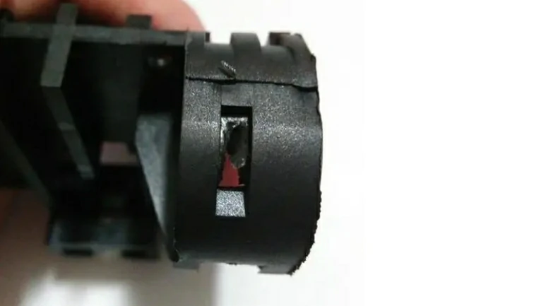
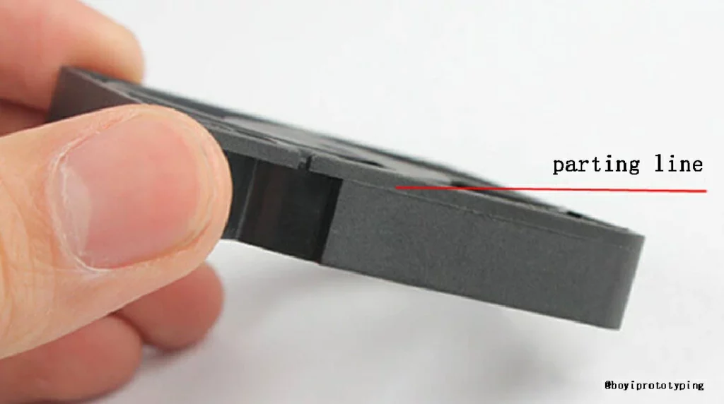
The boundary where the parting line intersects the plastic part’s surface is called the parting line (PL). Since the contact between mold modules cannot be completely gap-free, a seam appears on the plastic part where the parting surfaces meet, forming a line known as the parting line or seam line.
Importance of Parting Lines
Parting lines play a significant role in several aspects of injection molding:
- Aesthetic Quality: Visible parting lines can impact the appearance of the final product. For consumer goods, a poorly placed or noticeable parting line can be perceived as a defect.
- Dimensional Accuracy: Parting lines must be designed to ensure minimal flash, which is excess material that can form along the parting line. Flash must be trimmed, which adds extra steps and costs.
- Structural Integrity: Incorrect placement of parting lines can weaken the part or create stress concentrations that may lead to part failure under load.
- Mold Construction: The location of the parting line affects the complexity and cost of the mold. A strategically placed parting line can simplify mold construction and reduce costs.
Specific Location of the Parting Line After Molding
The parting line is an unavoidable phenomenon in the injection molding process. The most common location is at the maximum contour of the plastic part. The mold’s parting surface is usually designed here because it facilitates the opening of the mold and the removal of the plastic part. For simple geometries, the parting line will appear on the outer edges of the plastic part.
If the plastic part has holes or grooves, the parting line may appear at the edges of these features. This design can facilitate the movement of sliders or other moving modules in the mold. For plastic parts with complex geometries, the parting line may follow the edges of protrusions and recesses to allow the mold to separate.
Types of Parting Lines in Injection Molding
Parting lines in injection molding can vary based on the complexity and design requirements of the plastic part. Here are the common types of parting lines used in the industry:
Straight Parting Line
The simplest type of parting line where the mold halves separate along a flat plane. It is ideal for parts with basic geometries and flat surfaces. Examples include rectangular boxes, flat panels, or cylindrical shapes without undercuts. While suitable for simple shapes, straight parting lines may not accommodate complex geometries or parts with undercuts efficiently.

Advantages:
- Cost Efficiency: Straight parting lines are easier and cheaper to manufacture because they require less complex mold designs.
- Ease of Alignment: They facilitate easier alignment of mold halves during assembly and maintenance.
Curved Parting Line
Curved parting lines follow the contours of the part, allowing for a better fit around rounded or irregular shapes. This type is used for parts with complex geometries that cannot be released with a straight parting line. Examples include automotive body panels, curved handles, or organic shapes. More complex to design and manufacture compared to straight parting lines, resulting in higher mold costs and maintenance requirements.
Advantages:
- Improved Aesthetics: Curved parting lines provide a seamless appearance and reduce visible seam lines on the finished part.
- Functionality: They accommodate parts with varying thicknesses or complex designs more effectively.
Stepped Parting Line
A non-planar parting line with steps or levels to accommodate different features or heights in the part. Suitable for parts with varying levels or features that need to be molded in a single piece. The direction of this sliding is illustrated in the diagram below. Therefore, it is advisable to initially select the parting surface with a stepped profile (the side with the larger vertical projection area), as shown in the diagram on the right below.

Advantages:
- Design Flexibility: Allows for more intricate part designs without sacrificing moldability.
- Single-piece Molding: Facilitates molding of parts with complex internal features or varied heights in a single operation.
Comprehensive Parting Lines
Comprehensive parting lines are a design approach in injection molding where the parting surface integrates both flat and curved surfaces, or combines inclined and curved parting surfaces to form a unified parting line.
Advantages:
- Enhanced Mold Strength: Integrating multiple parting surfaces strategically can strengthen the mold structure, improving longevity and durability.
- Reduced Flash Formation: Smooth sealing surfaces help prevent flash, which is excess material that can occur at the parting line.
- Improved Machining Process: Smoothing out transitions between different parting surfaces minimizes steps and sharp corners, facilitating easier NC machining and reducing the need for EDM (Electrical Discharge Machining).
Beveled Parting Lines
Beveled parting lines feature an angled surface along the mold split, rather than a flat or perpendicular separation. The angle can vary depending on the design requirements of the part and the mold. Beveled parting lines can contribute to a cleaner and more aesthetically pleasing finish on the molded part, as compared to straight or sharp parting lines.
Advantages:
- Enhanced Mold Release: By reducing friction and minimizing surface contact, beveled parting lines facilitate smoother mold release, which can increase production efficiency and reduce cycle times.
- Improved Part Quality: They contribute to better surface finish and dimensional accuracy of the molded parts, as they minimize the risk of flash formation and parting line marks.
- Aesthetic Benefits: Beveled parting lines can improve the overall appearance of the part by reducing the visibility of the seam line, enhancing the product’s visual appeal.
Impact of Parting Lines on Product Quality
In the process of product and mold design, the influence of the parting line should be fully considered to ensure that the design of the parting line is reasonable, the position is appropriate, and the sealing performance is good, in order to improve the appearance quality of the product, sealing performance, and the service life of the mold.
- Appearance quality: The position and surface quality of the parting line directly affect the appearance quality of the product. Unreasonable parting line design may lead to injection molding defects such as burrs and pinch marks on the surface of the product, reducing its aesthetics and market competitiveness.
- Sealing performance: The sealing performance of the parting line is related to the tightness of the mold closure. If the design of the parting line is unreasonable or the sealing is poor, it may cause plastic leakage or flash during the injection process, affecting the dimensional accuracy and appearance quality of the product.
- Mold lifespan: The design of the parting line also affects the service life of the mold. Unreasonable parting line design may result in excessive stress or wear on the mold during use, shortening its service life.
Injection Molding Problem – There is a Flash on the Parting Line
During the injection molding process, the appearance of flash on the parting line is a common issue. Here are the possible causes and corresponding solutions for this problem:
Causes of Flash
- Excessive Injection Pressure: When the injection pressure is set too high, the plastic in the mold is subjected to excessive pressure, causing it to overflow from the parting line and form flash.
- Inadequate Mold Closure: If the mold does not close tightly enough, gaps exist between the parting surfaces, allowing plastic to escape and create flash during the injection process.
- Improper Mold Temperature Settings: Excessively high mold temperatures can increase the fluidity of the plastic, making it more prone to forming flash along the parting line.
- Insufficient Clamping Force: Clamping force is crucial for ensuring a tight closure of the mold. If the clamping force is insufficient, the mold may experience minor movements during injection, leading to the formation of flash.
- Issues with Plastic Raw Materials: High levels of volatiles, moisture, or other impurities in the plastic raw materials can also contribute to the appearance of flash.
Solutions
- Adjust Injection Pressure: Based on the specific product and mold design, appropriately reduce the injection pressure to decrease the pressure within the mold, thereby preventing the formation of flash.
- Check Mold Closure Accuracy: Regularly maintain and service the mold to ensure its closure accuracy meets requirements. If wear or deformation is found in the mold, repair or replace it promptly.
- Adjust Mold Temperature: Set the mold temperature reasonably based on the plastic’s characteristics and product requirements. Appropriately lowering the mold temperature can reduce the fluidity of the plastic, thus decreasing the likelihood of flash formation.
- Increase Clamping Force: Depending on the mold and product conditions, increase the clamping force to ensure the mold remains closed during the injection process, preventing flash formation.
- Optimize Plastic Raw Materials: Choose plastic raw materials with stable quality and strictly control the content of volatiles, moisture, and other impurities. Thoroughly dry and preprocess the raw materials before injection molding to minimize the occurrence of flash.
How to Design Parting Lines in Injection Molding?
Designing an effective parting line in injection molding involves a strategic approach to ensure the seamless production of high-quality plastic parts. Here are key considerations and steps involved in this process:
Understanding Mold Design and Line of Draw
The first step in designing a parting line is determining the mold’s opening direction relative to the part, known as the “line of draw.” This fundamental decision impacts where the parting line will be positioned on the product. It involves assessing how the mold halves will separate and how this separation will affect the final appearance and functionality of the molded part.
Minimizing Shrinkage and Distortion Effects
Plastics undergo shrinkage as they cool down after injection molding. Incorrect placement of the parting line can lead to dimensional inaccuracies, warping, or distortion of the final product. To mitigate these effects, draft angles (taper) are incorporated into vertical walls away from the parting line. This facilitates smooth ejection from the mold and reduces the risk of damaging critical features during release.
Preserving Functional Integrity and Component Placement
Careful consideration is given to the placement of functional components and features relative to the parting line. This ensures that critical features maintain their intended functionality post-molding. Proper alignment helps prevent features from shifting or becoming unusable due to shrinkage or misalignment during the molding process.
Utilizing Design for Manufacturability (DFM) Principles
DFM analysis plays a crucial role in optimizing parting line placement. It helps identify potential manufacturing flaws early in the design phase and suggests optimal locations for the parting line. By applying DFM principles, designers can enhance manufacturing efficiency, reduce scrap rates, and minimize production costs associated with molding processes.
Designers Need to Have Additional Knowledge About Parting Lines
As designers and engineers, it is crucial to consider the directionality of parting lines during the design phase, especially for components where determining the parting line is relatively straightforward. By considering the impact of parting lines on structural aspects such as dimensional accuracy, fit tolerances, and surface quality during the initial design stages, we can minimize the need for frequent modifications during Design for Manufacturing (DFM) and reduce issues encountered during trial molding that could have been preemptively avoided.
Of course, there are additional factors influencing the selection of parting lines beyond those mentioned above. By proactively assessing the influence of parting lines, we can effectively mitigate problems and adjustments during subsequent production processes. This approach not only enhances product quality and reduces injection molding costs but also ensures maximized production efficiency.
Challenges Faced with the Parting Line
As with anything in the injection molding process, the plastic parting line also poses several challenges. Here are a few common challenges faced by injection molding experts regarding the parting line:
- Complex Shapes: For plastics with complex shapes, determining the parting line becomes more difficult. It may not always be located in the middle of the part. Mold designers have to find a position that both satisfies the needs of the part designer and facilitates production. The parting line can take on different shapes and does not need to be a straight line. It can also be placed around certain edges of the part or in a subtle location that won’t be visible most of the time in the final product.
- Liquid Silicone Rubber (LSR) Components: The handling of liquid silicone rubber (LSR) components is even more complex. Molten LSR can squeeze into smaller gaps and may produce more burrs or thin excess plastic around the parting line. Achieving this is more difficult, but if designed properly, the parting line in LSR components can be smaller and harder to notice.
It’s important to note that while these challenges exist, with careful design and collaboration between part designers and mold makers, the parting line can be optimized to minimize its impact on the final product.
Conclusion
Parting lines are a fundamental aspect of injection molding that significantly influences the quality and manufacturability of plastic parts. By understanding the factors that affect parting line placement and employing best practices, manufacturers can produce high-quality parts with minimal defects.

Let’s Start A New Project Today
All information and uploads are secure and confidential.
FAQ
The parting line significantly impacts mold design complexity. It determines the number and type of mold components required, affects assembly and maintenance considerations, and influences the overall cost and manufacturability of the mold.
The location of the parting line influences the design, functionality, and appearance of the molded part. It must be strategically placed to avoid interfering with critical features, ensuring uniform material flow, and minimizing visible seams or flash on the final product.
Catalog: Injection Molding Guide

This article was written by engineers from the BOYI team. Fuquan Chen is a professional engineer and technical expert with 20 years of experience in rapid prototyping, mold manufacturing, and plastic injection molding.