Injection molding stands out as a fast and efficient method for producing plastic parts at scale. Central to this process is the injection mold, comprising two primary components: the core and the cavity. These halves of the mold join together to form a closed tool into which molten plastic is injected.
Upon cooling and solidification, the mold opens, allowing for the removal of the finished part. Depending on mold construction and production needs, this cycle can repeat tens, hundreds, or thousands of times.
This guide outlines key considerations and best practices for designing plastic parts for injection molding.
Design Principles
1.Wall Thickness
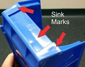
Wall thickness is a critical design consideration in injection molding, impacting the strength, cost, and appearance of the molded part. Maintain uniform wall thickness to prevent defects like sink marks and warping.
Importance of Uniform Wall Thickness
Uniform wall thickness is highly recommended in injection molded parts. It promotes consistent cooling during the molding process, which helps minimize shrinkage and reduces the likelihood of defects such as warping and sink marks. When walls have varying thicknesses, they cool and solidify at different rates, leading to uneven stresses and potential injection molding defects in the final part.
Nominal Wall Thickness
Nominal wall thickness refers to the intended thickness throughout the part design. While uniformity is ideal, it’s crucial to avoid walls that are excessively thick or thin:
- Excessively thick walls require more material, increasing material costs and prolonging cycle times, which can escalate production costs.
- Excessively thin walls may result in inadequate filling of the mold cavity, leading to incomplete parts or ‘short shots’. This occurs when the molten plastic cannot completely fill the mold due to insufficient flow into thinner sections.
Recommended Wall Thicknesses for Common Plastic Resins
Here are the recommended ranges of wall thickness for various plastic materials commonly used in injection molding:
| esin | Recommended Wall Thickness (inches) | Recommended Wall Thickness (mm) |
|---|---|---|
| Polybutylene Terephthalate (PBT) | 0.080–0.250 | 2.032–6.350 |
| Polyethylene (PE) | 0.030–0.200 | 0.76–5.08 |
| Polycarbonate (PC) | 0.040–0.150 | 1.02–3.81 |
| Acetal (POM) | 0.030–0.120 | 0.76–3.05 |
| Polyether Ether Ketone (PEEK) | 0.020–0.200 | 0.508–5.080 |
| Polypropylene (PP) | 0.040–0.150 | 1.02–3.81 |
| Acrylonitrile Butadiene Styrene (ABS) | 0.045–0.140 | 1.14–3.56 |
| Polyphenylsulfone (PPSU) | 0.030–0.250 | 0.762–6.350 |
| Thermoplastic Polyurethane (TPU) | 0.025–0.125 | 0.64–3.18 |
| Nylon (PA) | 0.030–0.115 | 0.76–2.92 |
| Polyetherimide (PEI) | 0.080–0.120 | 2.032–3.048 |
| Polystyrene (PS) | 0.025–0.125 | 0.64–3.18 |
| Acrylic (PMMA) | 0.025–0.150 | 0.64–3.81 |
| Thermoplastic Elastomer (TPE) | 0.025–0.125 | 0.64–3.18 |
| Polyvinyl Chloride (PVC) | 0.035–0.250 | 0.89–6.35 |
| Polyethylene Terephthalate (PET) | 0.025–0.150 | 0.64–3.81 |
Tips for Managing Wall Thickness Variation
If uniform wall thickness is not achievable throughout the design, consider incorporating smooth transitions between sections with different thicknesses. This design strategy helps to minimize stress concentrations and improves the overall structural integrity of the molded part.
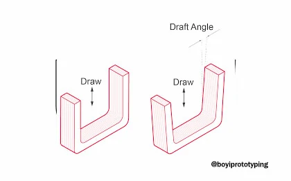
2.Draft Angles
A draft angle is a taper applied to the vertical surfaces of a molded part to facilitate its removal from the mold. This slight angle, typically ranging from 1 to 5 degrees, ensures that parts eject smoothly, reducing the likelihood of damage and minimizing wear on the mold. Implementing appropriate draft angles can also decrease cooling times, which helps in controlling production costs.
Key Considerations for Specifying Draft Angles
When determining the appropriate draft angle for your design, consider the following factors:
- Material Type: Different resins or injection molding materials require varying draft angles due to their unique shrinkage and flow properties. For example, softer plastics may need more draft than harder plastics to avoid sticking.
- Industry Standards: Various industry standards guide the appropriate amount of draft based on the type of finish and texture required. Organizations such as the Society of the Plastics Industry (SPI) and the Society of German Engineers (VDI) provide guidelines for draft angles associated with different finishes.
- Surface Finish: The texture and polish of the molded part’s surface affect the required draft angle. Smoother finishes necessitate less draft, while rougher, textured finishes need more draft to prevent the part from sticking to the mold.
- Mold Design: The construction and operation of the mold also influence draft requirements. Consider the direction in which the mold separates (the draw) and ensure the draft angles facilitate easy ejection of the part.
Draft Angle Guidelines Based on Surface Finish
The amount of draft needed depends significantly on the desired surface finish of the part:
- Smooth Finish: Generally requires 1 to 2 degrees of draft.
- Light Texture: Typically needs around 3 degrees of draft.
- Heavy Texture: Often requires 5 degrees or more of draft.
As a rule of thumb, for textured surfaces, add about 1.5° of draft for every 0.001” (0.025 mm) of texture depth. Reference tables from organizations like SPI, VDI, Mold-Tech (MT), and Yick Sang (YS) can provide specific recommendations for various textures.
Practical Considerations for Mold Construction
To ensure effective molding and ejection, draft angles must align with the mold’s construction and draw direction:
- Ejector System: Parts should release easily from the half of the mold containing the ejector system. Misaligned draft angles can cause parts to stick in the wrong section, complicating ejection.
- Feature Drafting: Vertical features, such as through-holes, should be drafted toward the core side of the mold where the ejector system is located. For example, in a rectangular part with through-holes, drafting the holes toward the cavity side could lead to sticking issues, whereas drafting them toward the core facilitates easier ejection.
3.Ribs and Bosses
Injection molded parts often feature thin walls to promote faster production cycles and extend mold life. Use ribs for structural support and bosses for attachment points, maintain adequate thickness and fillet radii to avoid stress concentrations. However, these thin-walled parts may lack sufficient strength.
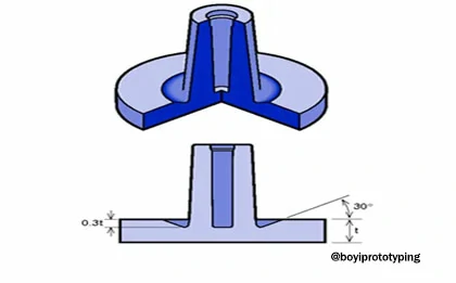
Ribs
Ribs are vertical structures that provide additional support and improve the load-bearing capacity of injection molded parts. However, improperly designed ribs can lead to issues such as shrinkage and sink marks. To optimize rib design, consider the following guidelines:
- Wall Thickness: Ensure that the rib’s wall thickness is 50% to 60% (0.5 to 0.6 T) of the nominal wall thickness (T). This helps maintain strength without causing excessive shrinkage or sink marks on the opposite side of the rib.
- Fillets: Add fillets at the base of ribs to reduce stress concentrations. The radius of the fillet should be between 0.25T and 0.5T, but should not exceed 0.010 inches to avoid compromising the part’s finish and structural integrity.
- Height: Keep ribs as short as possible and do not exceed a height of 2.5T. If additional height is required, consider using multiple shorter ribs instead of a single tall rib to distribute the load more effectively.
- Draft Angles: Apply a draft angle to ribs, typically at least 0.5 degrees per side, to facilitate easy ejection from the mold and prevent damage to the part.
Bosses
Bosses are vertical structures used to support assembly and enhance the structural integrity of injection molded parts. They are designed to accommodate fasteners like screws and can be used in conjunction with other features for added strength. Consider the following best practices when designing bosses:
- Location: Place bosses in areas where additional structural integrity is required, such as near screw slots or attachment points. Proper placement ensures that the part can withstand the forces applied during assembly and use.
- Diameter: Avoid making boss holes too small, as they will shrink during cooling. A larger diameter helps maintain the intended size and fit for fasteners or inserts.
- Thickness: To prevent sink marks, the boss thickness should be no more than 60% of the overall wall thickness. This balance maintains part aesthetics and structural integrity.
- Attachment to Walls: Ensure bosses are properly aligned with walls and other features. Misalignment can lead to assembly issues and reduce the overall strength of the part.
These guidelines help avoid common issues such as shrinkage, sink marks, and misalignment, ensuring a high-quality final product.
4.Optimizing Corners
Sharp corners in injection molded parts can significantly affect both the structural integrity and the manufacturing cost of the part. These corners not only act as stress concentrators, leading to potential part failure, but also necessitate more complex and expensive mold-making techniques, such as electrical discharge machining (EDM).
While sharp corners are sometimes unavoidable and can be useful for defining parting lines, it is generally preferable to replace them with rounded corners whenever possible.
Benefits of Rounded Corners
- Stress Reduction: Rounded corners help distribute stress more evenly across the part, minimizing the risk of cracks and breaks under load. This is especially important in high-stress applications where durability and reliability are critical.
- Consistent Shrinkage: Rounded corners reduce variations in shrinkage rates during cooling, leading to more dimensionally stable parts. This consistency is vital for maintaining tight tolerances and achieving high-quality end products.
- Cost Efficiency: Using rounded corners can lower tooling costs. Molds with rounded features are easier and cheaper to manufacture and maintain, resulting in cost savings over the production lifecycle.
- Improved Flow: Rounded corners facilitate better flow of molten plastic within the mold, reducing the likelihood of voids and ensuring complete filling of the mold cavity.
Guidelines for Applying Rounded Corners
To maximize the benefits of rounded corners, consider the following design guidelines:
- Internal Radii: Ensure the internal radius is at least 50% of the wall thickness. This helps to minimize stress concentrations and promotes smoother material flow.
- External Radii: The external radius should be the sum of the internal radius and the wall thickness. This creates a balanced transition that supports the structural integrity of the part.
- Uniform Transition: Start the internal and external corner radii from the same point. This uniformity helps maintain consistent wall thickness and reduces potential weak points in the part.
Practical Considerations
- Tooling and Manufacturing: Incorporating these guidelines into your part design not only improves part performance but also simplifies the tooling process. Molds with rounded features are less prone to wear and tear, extending their operational lifespan and reducing maintenance costs.
- Design Flexibility: While rounded corners are generally preferable, there are instances where sharp edges are necessary for functional or aesthetic reasons. In such cases, careful consideration of stress distribution and manufacturing techniques is essential to mitigate potential drawbacks.
5.Achieving Smooth Transitions
Smooth transitions help distribute stress evenly across the part, reducing the risk of failure due to localized stress concentrations. This practice enhances the overall structural integrity and longevity of injection molded parts.
Methods for Achieving Smooth Transitions
Chamfers and Fillets
- Chamfers: Chamfers are angled edges where two surfaces meet. They are effective in easing the transition between different wall thicknesses while maintaining structural integrity. Chamfers not only reduce stress concentrations but also facilitate easier mold release during the ejection process.
- Fillets: Fillets are rounded corners or edges that replace sharp corners. They serve to distribute stress more evenly across the part, minimizing stress risers that could lead to cracks or breaks under load. Fillets are particularly effective in areas where abrupt changes in thickness occur, ensuring smoother flow of molten plastic during injection.
Additional Considerations
- Design Guidelines: Adhering to design guidelines that specify minimum radii for chamfers and fillets ensures optimal performance and manufacturability of injection molded parts.
- Material Compatibility: Consider the material properties and mold design when selecting the size and type of transition. Different plastics may require varying degrees of transition to achieve optimal mechanical properties.
- Aesthetic and Functional Benefits: Beyond stress reduction, smooth transitions enhance the aesthetic appeal of parts and improve functionality by reducing potential for warping or distortion during cooling.
Practical Applications
Implementing chamfers and fillets in part design not only improves mechanical performance but also enhances the overall quality and reliability of injection molded products. These transitions are essential for meeting stringent tolerances and performance requirements across various industries, from automotive components to consumer electronics.
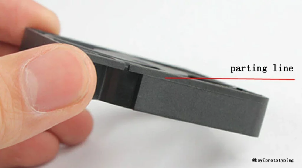
6.Parting Lines
One crucial aspect of mold design is the parting line, which determines where the mold opens and closes during the injection cycle.
Conventionally, designers tend to envision parting lines bisecting the center of a molded part, primarily due to simplicity. However, in reality, this approach is not always practical or aesthetically pleasing. The parting line is strategically positioned along the bottom edges of the brick, ensuring it remains concealed during normal use.
When considering parting line placement, several factors come into play. Sharp edges, while prone to stress concentration, are favorable for parting lines because they simplify mold construction. This simplicity translates into lower costs and faster production cycles. However, it’s crucial to avoid filleted surfaces as parting line locations.
Fillets require tighter tolerances in mold construction, leading to increased costs. Furthermore, they increase the risk of flash, a common injection molding defect that occurs when the mold halves do not align perfectly.
Optimal parting line placement involves a delicate balancing act between design considerations, manufacturability, and aesthetics. Here are some key points to consider:
- Aesthetics: The parting line should be positioned in a way that minimizes its visibility in the final product. This often involves positioning it in less conspicuous areas or along edges that are not easily noticed.
- Functionality: The parting line should not interfere with the intended use or functionality of the part. For example, in the case of the LEGO® brick, positioning the parting line along the bottom edges ensures it does not compromise the brick’s interlocking capabilities.
- Manufacturability: Simplicity is key when designing the parting line. Avoiding complex geometries and tight tolerances can reduce costs and improve mold durability.
- Material Considerations: The choice of material also influences parting line placement. Some materials may require specific parting line configurations to ensure proper flow and cooling during the injection process.
- Post-Processing: Consider the impact of post-processing operations on the parting line. For example, if the part will undergo painting or coating, the parting line may require special attention to ensure a smooth finish.
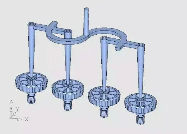
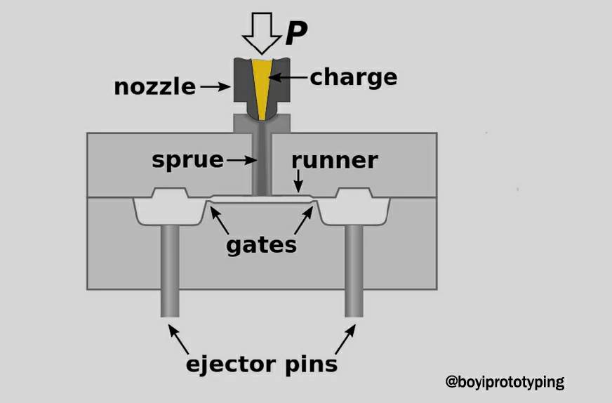
7.Ejector Pins
Ejector pins play a critical role in the injection molding process by pushing the cooled part out of the mold. This step, while seemingly simple, requires careful consideration to prevent damage to the part and ensure a smooth ejection process.
Function of Ejector Pins
Ejector pins are typically cylindrical rods placed within the mold. When the molding cycle is complete, and the plastic part has solidified, the mold opens, and the ejector pins push the part out of the cavity. This mechanism is essential to prepare the mold for the next cycle and to maintain production efficiency.
Best Practices for Ejector Pin Placement
To ensure that the ejection process does not compromise the part quality, follow these best practices for ejector pin placement:
- Invisible Surfaces: Place ejector pins on areas of the part that are not visible in the final product. This minimizes the appearance of ejector pin marks, which can detract from the part’s aesthetic appeal.
- Even Distribution: Distribute the ejection force as uniformly as possible across the part. This helps to prevent deformation or warping, which can occur if the force is concentrated in one area.
- Strong Areas: Apply the ejection force to the parts of the design that have the greatest strength and rigidity. This ensures that the force does not cause cracks or breaks in weaker sections.
- Avoid Thin Sections: Avoid placing ejector pins on thin or delicate areas of the part. These regions are more susceptible to damage during the ejection process.
- Stay Clear of Sloped Surfaces: Avoid locating ejector pins on sloped surfaces, as this can cause uneven force application and potential part distortion.
- Distance from Sliding Tracks: Place ejector pins away from the sliding tracks of the mold. Interference with these tracks can impede the smooth operation of the mold and affect part quality.
Additional Considerations
Beyond basic placement, there are several additional factors that designers and mold makers should consider to optimize ejector pin performance:
- Ejection Force: Use an ejection mechanism that provides adequate force to eject the part without causing damage. The system should also have sufficient wear resistance to maintain performance over many cycles.
- Pin Design: The design and material of the ejector pins should be selected based on the specific requirements of the part and mold. Pins need to be robust enough to withstand repeated use without bending or breaking.
- Cooling Time: Ensure that the part has fully cooled before ejection to reduce the risk of deformation. Inadequate cooling can lead to parts that are too soft to withstand the ejection force.
- Surface Finish: Consider the finish of the part and how ejector pin marks might affect it. For high-precision or cosmetic parts, additional steps may be needed to minimize or eliminate visible marks.
- Maintenance: Regular maintenance of the ejector pin mechanism is crucial. Over time, pins can wear down or become misaligned, leading to ejection issues. Routine checks and replacements can help maintain consistent part quality.
BOYI is an expert in plastic injection molding and mold manufacturing. As you refine your part design, remember to upload your design and get expert DFM feedback from BOYI to ensure all aspects of your injection molding project are thoroughly evaluated and optimized.
Let’s Start A New Project Today
Our engineers will contact you within 2 hours.
Part Geometry
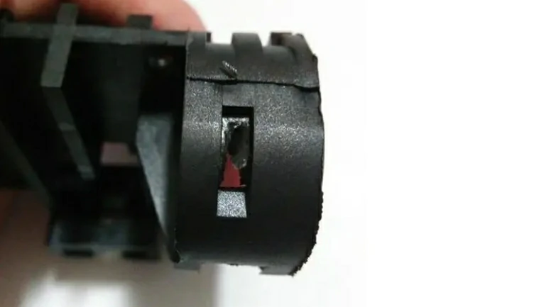
1.Undercuts
Undercuts in injection molding refer to features that prevent the part from being ejected from the mold due to their geometry. Undercuts are areas of a part that are recessed or protrude in such a way that they would trap the part in the mold if standard mold action is used. These features can be internal or external and include threads, holes, grooves, and projections that are perpendicular to the mold’s parting line.
Maximum Side Core Dimensions
| Width (inches/mm) | Height (inches/mm) | Pull (inches/mm) |
|---|---|---|
| < 8.42 in / 213.84 mm | < 2.38 in / 60.38 mm | < 2.90 in / 73.66 mm |
Strategies to Manage Undercuts
1. Design Modification
Whenever possible, modify the part design to eliminate or minimize undercuts. This can be achieved by:
- Redesigning Features: Adjust the design to avoid perpendicular features that create undercuts. For example, replace internal threads with external ones if possible.
- Using Assembly: Split the part into multiple pieces that can be assembled post-molding. This can eliminate the need for undercuts in the mold.
2. Use of Slides
Slides are mold components that move sideways when the mold opens, allowing the part to be released. They are used to handle side-action features such as holes or slots.
- Mechanism: Slides are typically cam-actuated. When the mold opens, the cam mechanism pulls the slide away from the undercut, freeing the part.
- Applications: Ideal for parts with side holes, side slots, or other lateral features.
3. Lifters
Lifters are used to release internal undercuts by moving upwards and out of the way when the mold opens.
- Mechanism: Lifters are often spring-loaded or hydraulically actuated, moving perpendicularly to the mold’s parting line.
- Applications: Suitable for internal features like hooks, snaps, or retaining clips.
4. Collapsible Cores
Collapsible cores are specialized mold components that can collapse inward to release complex internal features like threads.
- Mechanism: These cores are typically mechanical and retract into themselves when the mold opens, allowing the part to be ejected without damaging the internal geometry.
- Applications: Primarily used for parts with internal threads or intricate internal geometries.
By minimizing or eliminating undercuts wherever possible and employing slides, lifters, or collapsible cores for complex geometries, designers can streamline the mold design and production process, resulting in cost-effective and high-quality parts. As you refine your design, consult with BOYI injection molding experts to ensure all aspects of the undercut management are optimized for your specific application.
2.Fillets and Radii
Fillets are rounded transitions between two surfaces, while radii refer to the curvature at edges or corners of a part. Proper application of these features can significantly impact the performance and manufacturability of the molded parts.
Before Implementation
A part with sharp internal corners and no fillets was experiencing issues with incomplete filling and high rejection rates due to stress fractures.
After Implementation
By incorporating fillets with a radius of 0.5mm at internal corners and applying radii to all external edges, the part showed significant improvements:
- Complete Mold Filling: The molten plastic flowed more smoothly, filling the mold cavity completely.
- Reduced Stress Fractures: Stress concentrations were minimized, resulting in fewer part failures.
- Easier Ejection: The parts were easier to eject from the mold, reducing cycle time and improving overall efficiency.
3.Surface Finish
Specifying the desired surface finish, often guided by industry standards like SPI (Society of the Plastics Industry), ensures that parts meet design requirements and perform effectively in their intended applications.
SPI Finish Standards
The SPI provides a widely accepted set of standards for specifying surface finishes in injection molding. These standards categorize finishes based on their smoothness and texture, helping designers and manufacturers achieve consistent results.
Common SPI Finish Classes
| Class | Description |
|---|---|
| SPI-A | High gloss finish suitable for optical parts or parts requiring high clarity. |
| SPI-B | Medium gloss finish with minimal texture, suitable for parts requiring good appearance. |
| SPI-C | Fine matte finish, ideal for parts where texture is acceptable but appearance is still important. |
| SPI-D | Course matte finish, suitable for parts where texture is not critical and cost efficiency is prioritized. |
Selecting the Right Surface Finish
- Functional Requirements: Consider the functional requirements of the part. For instance, parts requiring low friction might benefit from a smoother finish (e.g., SPI-A or SPI-B).
- Aesthetic Requirements: Determine the desired visual appearance. Consumer products often require higher gloss finishes (SPI-A or SPI-B), while industrial parts may suffice with a matte finish (SPI-C or SPI-D).
- Mold Considerations: Choose a surface finish that aligns with the mold’s capabilities and the production process. Finer finishes may require more intricate mold polishing techniques, impacting manufacturing costs.
4.Tolerances
When designing injection-molded parts for larger assemblies, achieving precise and consistent dimensions is critical. Dimensional deviations are inherent in any manufacturing process, and defining acceptable variations, known as tolerances, is essential. Proper tolerance design ensures that parts fit together correctly and function as intended in their final applications.
Types of Injection Molding Tolerances
There are two primary types of tolerances used in injection molding:
Commercial Tolerances:
- Characteristics: These tolerances are less stringent and typically involve lower-cost molds and production processes. Parts manufactured with commercial tolerances are more economical, making them suitable for applications where extreme precision is not critical.
- Applications: Commonly used in consumer products and non-critical applications where minor dimensional variations do not significantly impact performance.
Fine Tolerances:
- Characteristics: Fine tolerances demand higher precision, necessitating the use of more expensive molds and tighter production controls. Parts produced with fine tolerances are typically more costly but offer superior accuracy and consistency.
- Applications: Ideal for high-precision applications, such as medical devices, aerospace components, and high-performance industrial parts.
Tolerance Stack-Up in Assemblies
When designing assemblies consisting of multiple injection-molded parts, it is crucial to consider tolerance stack-up. Tolerance stack-up refers to the cumulative effect of individual part tolerances on the overall assembly. Properly managing tolerance stack-up ensures that all components fit together as intended, even when each part is within its specified tolerance range.
Example of Tolerance Stack-Up:
- Scenario: An assembly includes three parts, each with a screw hole. Each hole is within tolerance individually, but the alignment of all three holes is critical for the screw to pass through.
- Solution: By carefully controlling the tolerances of each hole and considering the cumulative effect, designers can ensure that the holes align properly, allowing for correct assembly.
Best Practices for Tolerance Design
To achieve optimal tolerance design in injection molding, follow these best practices:
- Material Selection: Choose the appropriate resin for the application, considering its shrinkage properties and how it affects dimensional stability.
- Design for Manufacturability (DFM): Collaborate with mold designers and manufacturers early in the design process to ensure tolerances are achievable and cost-effective.
- Consistent Communication: Clearly communicate tolerance requirements and expectations to all stakeholders, including designers, mold makers, and manufacturers.
- Iterative Testing: Conduct iterative testing and validation of parts to identify and address any tolerance-related issues before full-scale production.
Material Selection
Injection molding offers a versatile range of materials, each tailored to specific end-use applications, offering unique properties and processing requirements. It is crucial to choose the appropriate materials according to the application in injection molding design.
| Plastic Material | Characteristics |
|---|---|
| Polypropylene (PP) | Excellent chemical resistance, durability in wet environments. |
| Polycarbonate (PC) | Exceptional impact resistance, optical clarity, suitable for safety glasses and electronic components. |
| Acrylonitrile Butadiene Styrene (ABS) | High strength, impact resistance, used in electronics and automotive parts. |
| Polyethylene (PE) | Various densities, chemical resistance, widely used in packaging and pipes. |
| Polyether Ether Ketone (PEEK) | Excellent mechanical properties, high heat resistance, chemical stability, aerospace and medical applications. |
| Acrylic (PMMA) | Optical clarity, UV resistance, scratch resistance, signage and automotive applications. |
| Nylon (PA) | Toughness, high heat resistance, abrasion resistance, gears and structural components. |
| Polyphenylsulfone (PPSU) | High toughness, superior chemical resistance, high temperature resistance, medical instruments and plumbing. |
| Polybutylene Terephthalate (PBT) | Creep and fatigue resistance, electrical connectors, automotive parts. |
| Polystyrene (PS) | Lightweight, cost-effective, used in packaging and insulation boards. |
| Polyetherimide (PEI) | Stiffness, high heat resistance, flame retardancy, electronics and automotive applications. |
| Polyvinyl Chloride (PVC) | Excellent chemical resistance, weatherability, construction and medical applications. |
| Thermoplastic Polyurethane (TPU) | Elasticity, abrasion resistance, footwear and automotive interiors. |
| Acetal (POM) | Dimensional stability, low friction, chemical resistance, precision mechanical parts and gears. |
| Thermoplastic Elastomer (TPE) | Rubber-like properties, processing ease of plastic, automotive seals and soft-touch grips. |
| Polyethylene Terephthalate (PET) | Clarity, strength, recyclability, beverage bottles, food packaging, textile fibers. |
Considerations for Material Selection
- Mechanical Properties: Consider strength, toughness, flexibility, and impact resistance based on application requirements.
- Environmental and Chemical Resistance: Evaluate resistance to heat, chemicals, UV exposure, and moisture.
- Aesthetics: Opt for materials with optical clarity, colorability, and surface finish suitability.
- Processing Requirements: Ensure compatibility with injection molding processes, including melt flow characteristics and shrinkage rates.
- Cost and Availability: Balance material cost with performance requirements and availability in various grades (e.g., reinforced with fibers).
Advanced Material Grades
- Glass Fiber Reinforced: Enhances strength, stiffness, and dimensional stability.
- Carbon Fiber Reinforced: Offers superior strength-to-weight ratio, ideal for lightweight and high-performance applications.
- Flame Retardant: Includes additives for improved fire resistance, crucial for electronics and automotive applications.
Choosing the right material for injection molding involves careful consideration of performance, processing, and cost factors. By understanding the unique properties of each resin and their suitability for different applications, designers can optimize part design and manufacturing efficiency.
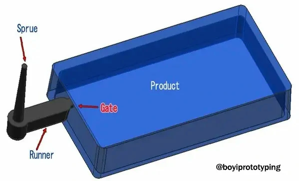
Gate Design
Gates are crucial components in the injection molding process, serving as the pathways through which molten plastic enters the mold cavity. The design and placement of gates significantly impact the quality and characteristics of the molded part. This guide explores the importance of gate size and location, different types of gates, and best practices for optimizing gate design.
Importance of Gate Size
The size of the gate is critical because it determines the volume and speed of the molten plastic entering the mold. Larger parts require larger gates to ensure adequate flow and to fill the cavity quickly and efficiently. If the gate is too small, it can restrict the flow, leading to incomplete filling, air entrapment, and other defects.
Importance of Gate Location
The location of the gate is equally important as it influences the flow pattern of the molten plastic, which in turn affects the quality and appearance of the final part. Poor gate placement can result in issues such as:
- Warping: Uneven cooling rates due to improper gate placement can cause parts to warp.
- Weld Lines: These are formed where two flow fronts meet and can weaken the part.
- Sink Marks: These depressions occur when there is insufficient packing pressure near the gate.
- Voids: Trapped air can create voids within the part.
- Gate Vestiges: Excess material protruding from the gate location that requires trimming.
Gate Design Considerations
When designing gates, consider the following factors to minimize defects and optimize part quality:
- Surface Marks: Place gates where any remaining marks after trimming are least noticeable, often along the parting line.
- Flow Characteristics: Ensure the gate supports a smooth and uniform flow into the cavity to reduce stress and prevent defects.
- Trimming Requirements: Choose gates that balance ease of trimming with the specific needs of the part, whether manual or automatic trimming is required.
Types of Injection Molding Gates
Gates can be broadly categorized based on their trimming methods: manually trimmed gates and automatically trimmed gates.
Manually Trimmed Gates
1.Edge or Standard Gates:
- Description: Rectangular cross-section, often tapered.
- Usage: Suitable for flat parts.
- Advantages: Simple design, easy to implement.
2.Fan Gates:
- Description: Large opening with variable thickness.
- Usage: Ideal for large parts and fragile mold sections.
- Advantages: Rapid filling, distributes material evenly.
3.Tab Gates:
- Description: Includes a tab-like feature to confine shear stresses.
- Usage: Thin, flat parts requiring low shear stresses.
- Advantages: Reduces stress concentration in the part.
4.Direct or Sprue Gates:
- Description: Feeds material directly into the cavity.
- Usage: Large, cylindrical parts.
- Advantages: High volume flow, simple design.
5.Disc or Diaphragm Gates:
- Description: Used for round or cylindrical parts requiring concentricity.
- Usage: Round or cylindrical parts.
- Advantages: Ensures uniform flow, though difficult to trim and remove.
6.Ring Gates:
- Description: Allows material to flow freely before entering a tube-like extension.
- Usage: Parts requiring uniform material distribution.
- Advantages: Consistent fill, suitable for complex shapes.
7.Spoke Gates:
- Description: Round gates with a cross in the middle.
- Usage: Tube-shaped parts.
- Advantages: Enables multi-point injection, though perfect concentricity is challenging.
Automatically Trimmed Gates
1.Hot Tip Gates:
- Description: Support conical or round shapes with uniform flow.
- Usage: Hot runner systems.
- Advantages: Keeps plastic molten until it enters the cavity, reducing waste and cycle time.
2.Submarine or Sub Gates:
- Description: Tapered channel that helps hide gate blemishes.
- Usage: Applications requiring minimal surface marks.
- Advantages: Reduces gate vestiges, suitable for high cosmetic requirements.
3.Pin Gates:
- Description: Used with fast-flowing resins.
- Usage: Parts requiring high cosmetic quality.
- Advantages: Minimizes visible vestiges, suitable for intricate parts.
Best Practices for Gate Design
To optimize gate design, follow these best practices:
- Balance Flow: Ensure the gate design promotes uniform flow throughout the mold cavity to minimize stress and defects.
- Optimize Location: Place gates where the impact of any remaining marks is minimized and where flow patterns will support high-quality part production.
- Choose Appropriate Type: Select the gate type that best suits the part’s geometry, material, and cosmetic requirements.
- Consider Trimming: Balance the ease of trimming with the need for precise, clean part surfaces.
Effective gate design in injection molding is essential for producing high-quality parts with minimal defects. By carefully considering gate size, location, and type, designers can optimize the flow of molten plastic, reduce stress concentrations, and ensure consistent part quality.
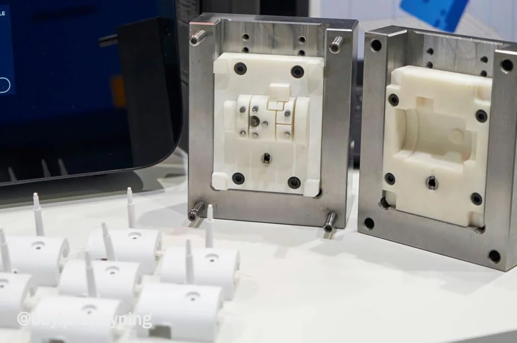
Tooling Considerations
Injection molding relies heavily on effective tooling design to ensure the production of high-quality plastic parts. Key aspects of tooling design include the selection of appropriate tool steels, the design of efficient cooling systems, and the optimization of the ejection system.
Tool Steel Selection
Choosing the right tool steel is crucial and depends on several factors such as production volume, material abrasiveness, and expected tool lifespan. For instance, P20 (1.2311) is commonly used for molds with lower production volumes due to its good polishability and machinability. In contrast, H13 (1.2344) is preferred for high-volume production runs and molds handling abrasive materials, thanks to its excellent thermal conductivity and wear resistance.
In environments prone to corrosion or high temperatures, stainless steels or tool steels with specialized coatings may be necessary to extend tool life and maintain part quality over time.
Cooling System Design
Efficient cooling is essential to control cycle times and ensure uniform part cooling, which directly impacts part quality and dimensional stability. Designing cooling channels that distribute heat evenly throughout the mold cavity helps prevent warping and reduces production cycle times. Conformal cooling designs, which conform to the mold contours, can further enhance cooling efficiency by optimizing heat dissipation.
Materials with high thermal conductivity, such as copper alloys, are often chosen for cooling channels to maximize heat transfer and minimize cooling time between molding cycles.
Ejection System Optimization
The ejection system is responsible for removing molded parts from the mold after they have cooled. Optimizing this system involves strategically placing ejector pins and considering alternative methods like air ejection to minimize part damage and reduce cycle times.
Properly positioned ejector pins should avoid areas with thin walls or complex geometries to prevent part deformation or sticking. Applying appropriate draft angles to mold surfaces helps ensure smooth ejection without compromising part integrity.
Integration and Case Study
Successful integration of these tooling considerations was demonstrated in a recent case study where a manufacturer of automotive components aimed to produce high-precision parts with complex geometries and tight tolerances. By selecting H13 tool steel for its wear resistance and thermal conductivity, and implementing conformal cooling channels, the manufacturer achieved a 20% reduction in cycle times while maintaining part quality.
Conclusion
Designing plastic parts for injection molding requires a thorough understanding of material properties, mold design principles, and manufacturing processes. By following these guidelines and collaborating closely with mold designers and manufacturers, you can optimize part design for efficient production and high-quality results.
BOYI specializes in precision injection molding and mold manufacturing services, delivering excellence through advanced technology and meticulous craftsmanship. With a commitment to quality and innovation, BOYI transforms concepts into reality, offering tailored solutions for diverse industrial needs.
Our state-of-the-art facilities and skilled team ensure precision at every step, from initial design to final production. Whether you require intricate parts or complex molds, BOYI’s expertise guarantees reliability and efficiency. We prioritize customer satisfaction, delivering superior results that meet stringent industry standards.
Partner with BOYI for your injection molding and mold manufacturing needs, and experience the difference of precision engineering and dedicated service. Trust BOYI to bring your vision to life with precision and reliability.
Let’s Start A New Project Today
Our engineers will contact you within 2 hours.
FAQ
Gate design plays a crucial role in the injection molding process as it affects part quality, cycle time, and tooling costs. Gates should ideally be placed at thick sections or areas with minimal aesthetic impact to minimize gate vestige. Selecting the appropriate gate type (e.g., edge gate, tunnel gate, hot runner) depends on the material and part design requirements to ensure optimal mold filling and part quality.
Undercuts complicate the ejection process in injection molding as they prevent the part from being smoothly ejected from the mold. Minimizing or eliminating undercuts in the design stage is essential to simplify mold design and reduce production costs. Complex geometries with undercuts may require additional mold features like slides, lifters, or collapsible cores to facilitate mold release.
Catalog: Injection Molding Guide

This article was written by engineers from the BOYI team. Fuquan Chen is a professional engineer and technical expert with 20 years of experience in rapid prototyping, mold manufacturing, and plastic injection molding.