Injection molding is a manufacturing process widely used for producing parts from thermoplastic and thermosetting plastic materials. One crucial component of the injection molding process is the ejector pin, which plays a vital role in the ejection of molded parts from the mold cavity.This article delves into the various types of ejector pins, their uses, and the materials they are made from.
Introduction to Ejector Pins
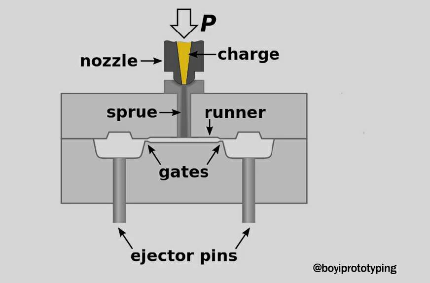
In injection molding, molten plastic is injected into a mold cavity to form a part. Once the part has cooled and solidified, it must be ejected from (or push out) the mold. This is where ejector pins come into play. Ejector pins are slender rods that apply force to eject the part from the mold, ensuring that it is released without damage. Ejector pins are typically cylindrical in shape with a rounded tip and are mounted in the ejector plate or in the movable half of the mold (known as the ejector half).
Types of Ejector Pins in Injection Molding
Ejector pins come in various types, each designed for specific applications and performance requirements. The primary types include:
1. Straight Ejector Pins
Straight ejector pins are the most fundamental and widely used type of ejector pins. They are characterized by their simple, cylindrical shape, with a uniform diameter along their entire length.
Features
- Uniform Diameter: The diameter of the pin remains constant from the base to the tip.
- Variety in Sizes: Available in multiple lengths and diameters to fit different mold requirements.
- Material: Typically made from hardened tool steel or other durable materials to withstand the stresses of ejection.
Applications
- General Purpose: Suitable for a broad range of standard injection molding applications.
- Simple Mold Designs: Ideal for molds that do not require specialized ejection techniques.
Advantages
- Simplicity: Easy to manufacture and replace, making them cost-effective.
- Versatility: Can be used in various molds, making them a go-to option for many manufacturers.
- Durability: Made from robust materials that offer long service life under typical molding conditions.

2. Step Ejector Pins
Step ejector pins have a distinctive design where the pin features a stepped change in diameter, typically transitioning from a larger base diameter to a smaller tip diameter.
Features
- Stepped Design: The transition between diameters helps in distributing ejection forces more evenly.
- Customizable Steps: The size and length of each step can be customized based on mold requirements.
- Enhanced Support: The step provides additional support and stability during ejection.
Applications
- Complex Mold Designs: Used in molds that require differentiated force application or support at specific points.
- Controlled Ejection: Ideal for parts that need varying ejection forces to avoid damage.
Advantages
- Improved Force Distribution: Reduces stress concentration on the part, minimizing the risk of damage.
- Precision: Allows for more precise control over the ejection process, enhancing part quality.
- Versatility: Can be adapted for specific mold configurations and requirements.
3. Blade Ejector Pins
Blade ejector pins, unlike cylindrical pins, have a flat, rectangular shape. This unique design makes them suitable for ejecting parts with delicate or thin-walled features.
Features
- Flat, Rectangular Shape: Provides a broad contact area, reducing the risk of damage to thin or fragile sections of the part.
- Thin Profile: Ideal for spaces where cylindrical pins cannot be used effectively.
- Sharp Edges: Designed to fit into narrow or intricate areas of the mold.
Applications
- Thin-Walled Parts: Effective for ejecting parts with thin walls that require gentle handling.
- Intricate Designs: Used for parts with delicate features that could be easily damaged by standard pins.
Advantages
- Reduced Damage: Minimizes the risk of damage to fragile or intricate parts.
- Precision: Allows for ejection from narrow or specific areas of the part.
- Specialized Use: Perfect for molds with specific ejection requirements due to their shape and size.
4. Sleeve Ejector Pins
Sleeve ejector pins consist of two components: an inner pin and an outer sleeve. This dual-component design is particularly useful for ejecting parts with internal features or cores.
Features
- Dual-Component Design: Combines an inner pin with an outer sleeve for enhanced ejection capability.
- Multiple Contact Points: Provides ejection force from multiple points simultaneously.
- Customization: Can be tailored to specific mold designs, including length and diameter variations.
Applications
- Complex Geometries: Suitable for parts with internal cavities or complex shapes that require uniform ejection.
- Simultaneous Ejection: Ensures parts are ejected evenly from multiple areas, reducing deformation risks.
Advantages
- Uniform Force Application: Provides balanced ejection, reducing the likelihood of warping or deformation.
- Enhanced Support: Supports intricate internal features during ejection.
- Versatility: Can be customized for various mold designs and part geometries.
5. Ejector Sleeves
Ejector sleeves are similar to sleeve ejector pins but typically cover a broader area and are larger in size. They provide additional support during ejection, particularly for large or thin parts.
Features
- Larger Coverage Area: Designed to cover a more extensive area of the part, providing enhanced support.
- Comprehensive Support: Supports the entire part during ejection to prevent warping or bending.
- Robust Design: Made from durable materials to handle the stresses of repeated ejections.
Applications
- Large Parts: Used for ejecting larger parts that need extra support to avoid damage.
- Thin Sections: Ideal for parts with large, thin sections that are prone to warping.
Advantages
- Enhanced Stability: Provides comprehensive support, reducing the risk of part damage.
- Effective for Thin Parts: Particularly useful for preventing deformation in thin or wide parts.
- Durability: Made from high-quality materials to ensure longevity and reliability.
Material of Ejector Pins
The choice of material for ejector pins is critical for their performance, durability, and suitability for specific molding applications. Each material offers distinct properties that can enhance the effectiveness of the injection molding process. Common materials include:
1. Tool Steel (H13, SKD61)
Tool steel is a broad category of carbon and alloy steels known for their hardness, wear resistance, and ability to hold a sharp edge. These properties make tool steel the most commonly used material for ejector pins.
Physical Properties
- Hardness: Tool steels typically have a Rockwell hardness of 60-65 HRC, providing excellent wear resistance.
- Tensile Strength: Ranges from 200,000 to 250,000 psi, allowing the pins to withstand high mechanical stresses.
- Thermal Conductivity: Moderate, usually around 20-30 W/m·K, adequate for most standard injection molding applications.
- Density: Approximately 7.8 g/cm³, which provides a balance of strength and durability.
Applications
- General Purpose: Suitable for a wide range of standard injection molding applications.
- High-Pressure Molding: Ideal for molds that operate under high pressure and temperature conditions.
Advantages
- Cost-Effective: Balances cost and performance, making it a popular choice for many applications.
- Wide Availability: Readily available in various sizes and grades.
- Reliable Performance: Provides consistent performance under typical molding conditions.
- High Wear Resistance: Suitable for prolonged use without significant wear.
- Good Toughness: Can handle the mechanical stresses during ejection without fracturing.
2. H13 Steel
H13 steel is a type of hot work tool steel known for its toughness, thermal stability, and ability to retain hardness at elevated temperatures. It is specially designed to perform well under high thermal and mechanical stress.
Physical Properties
- Hardness: After proper heat treatment, H13 steel achieves a hardness of 48-52 HRC.
- Tensile Strength: Approximately 285,000 psi, providing high strength to handle heavy loads.
- Thermal Conductivity: Around 28 W/m·K, which is good for maintaining structural integrity under high temperatures.
- Density: About 7.8 g/cm³, similar to other tool steels.
Applications
- High-Temperature Molding: Ideal for molds that operate at elevated temperatures.
- High-Stress Applications: Suitable for applications where ejector pins are subjected to significant mechanical and thermal stresses.
Advantages
- Thermal Stability: Retains hardness and strength at high temperatures, reducing deformation risks.
- High Toughness: Excellent impact resistance, making it suitable for high-stress applications.
3. Stainless Steel (420, 440C)
Stainless steel ejector pins are used in applications requiring corrosion resistance, such as when molding corrosive materials or in environments with high humidity. They are also chosen for their aesthetic appearance in certain applications.
Physical Properties
- Hardness: Varies depending on the grade, typically around 50-55 HRC.
- Tensile Strength: Generally ranges from 80,000 to 150,000 psi, lower than tool steel but sufficient for many applications.
- Thermal Conductivity: Lower than tool steels, approximately 15-25 W/m·K, but adequate for specific uses.
- Density: Around 7.9 g/cm³, slightly higher than tool steel, adding to its robustness.
Applications
- Corrosive Environments: Used in molds that process corrosive materials.
- High Humidity Conditions: Suitable for environments with high humidity levels.
- Aesthetic Applications: Chosen for applications where appearance matters.
Advantages
- Longevity: Resistant to corrosion, ensuring longer service life in corrosive environments.
- Aesthetic Appeal: Maintains a clean, polished appearance.
- Versatility: Can be used in various specialized applications requiring corrosion resistance.
4. Beryllium Copper
Beryllium copper is used for ejector pins that require high thermal conductivity. This material helps in rapidly dissipating heat from the molded part, reducing cooling time and improving cycle time efficiency.
Physical Properties
- Hardness: Can be heat treated to achieve 38-44 HRC.
- Tensile Strength: Around 200,000 psi, providing good strength for various applications.
- Thermal Conductivity: High, at approximately 100-130 W/m·K, significantly reducing cooling times.
- Density: About 8.25 g/cm³, slightly heavier than tool steels, which aids in maintaining dimensional stability.
Applications
- Rapid Cooling: Ideal for molds where quick cooling is essential to improve cycle time efficiency.
- Complex Molds: Used in molds with intricate designs that require precise temperature control.
Advantages
- Efficiency: Enhances production efficiency by reducing cooling times.
- Precision: Maintains dimensional stability due to excellent thermal properties.
- Durability: Combines strength and wear resistance for extended service life.
5. Tungsten Carbide
Tungsten carbide ejector pins are extremely hard and wear-resistant, making them suitable for high-volume production and abrasive materials. They offer exceptional durability but are more expensive than other materials.
Physical Properties
- Hardness: Extremely high, typically between 70-85 HRC, offering unparalleled wear resistance.
- Tensile Strength: Very high, approximately 500,000 psi, making it suitable for the most demanding applications.
- Thermal Conductivity: Around 60-100 W/m·K, providing good heat dissipation capabilities.
- Density: Very high, about 15.6 g/cm³, which contributes to its exceptional durability and wear resistance.
Applications
- High-Volume Production: Ideal for applications involving high-volume and continuous production.
- Abrasive Materials: Suitable for molds processing abrasive materials that would wear down other types of pins.
Advantages
- Longevity: Outstanding durability, reducing the need for frequent replacements.
- Performance: Maintains consistent performance under extreme conditions.
- Cost-Effective in the Long Run: While more expensive initially, the longevity and durability offer injection molding cost savings over time.
Table1: Comparison of physical performance
| Material | Hardness (HRC) | Tensile Strength (psi) | Thermal Conductivity (W/m·K) | Density (g/cm³) |
|---|---|---|---|---|
| Tool Steel | 60-65 | 200,000-250,000 | 20-30 | 7.8 |
| H13 Steel | 48-52 | 285,000 | 28 | 7.8 |
| Stainless Steel | 50-55 | 80,000-150,000 | 15-25 | 7.9 |
| Beryllium Copper | 38-44 | 200,000 | 100-130 | 8.25 |
| Tungsten Carbide | 70-85 | 500,000 | 60-100 | 15.6 |
Tool steel, H13 steel, stainless steel, beryllium copper, and tungsten carbide each offer unique advantages, making them suitable for different molding conditions and requirements. By considering factors such as hardness, tensile strength, thermal conductivity, and density, manufacturers can ensure optimal performance and longevity of their ejector pins.
Use of Ejector Pins
The primary function of ejector pins in injection molding is to facilitate the removal of the molded part from the mold cavity. After the plastic material has cooled and hardened to the desired shape, the ejector pins are activated, pushing the part out of the cavity. This process ensures that the part is removed safely and efficiently, without damaging either the part or the mold.
Considerations for Selecting Ejector Pins
Selecting the appropriate ejector pins is crucial in injection molding to ensure efficient ejection of molded parts while maintaining mold integrity and part quality. Here are key considerations to keep in mind:
- Use Larger Diameter Pins: Whenever possible and when there is sufficient ejection space, opt for ejector pins with larger diameters. Larger diameter pins provide better strength and durability, reducing the risk of deformation or breakage during ejection.
- Minimize Pin Variations: Choose ejector pins with standardized sizes to minimize variations. Prioritize selecting ejector pins from established size series to streamline inventory and maintenance.
- Meet Ejection Strength Requirements: Ejector pins must withstand significant pressure during ejection to ensure consistent and reliable operation. Avoid using undersized pins that may bend or deform under pressure.
- Support Pins for Small Diameters: For ejector pins with diameters below φ2.5, and where there is sufficient space, consider using support pins. Similarly, for core wall thicknesses less than 1mm or a wall diameter ratio ≤0.1, use supported core pins with longer supports for added stability.
- Effective Engagement Length: Ensure the effective engagement length of ejector pins is maintained at approximately (2.5~3) times the pin diameter (D), with a minimum length of 8mm. This ensures adequate contact and support during ejection.
- Positioning and Clearance: Typically, ejector pin faces should be positioned 0.03 to 0.05mm above the core plane. In cases where precise parting surfaces are required, consider adding recessed platforms around ejector pins for additional support and alignment.
- Flat Ejector Pins for Tall Ribs: For ejecting tall ribs (over 10mm in height), flat ejector pins are recommended to ensure proper ejection without damaging the part geometry.
- Positioning on Inclined Surfaces: When ejector pins are positioned on inclined surfaces, ensure they are properly located and fixed to prevent misalignment or movement during operation.

Adverse Effects of Ejector Pins
For plastic parts, when ejector pins push out the product, the product is still in a hot and soft state. Therefore, issues such as deformation, uneven surfaces, and residual burrs can occur at the ejector pin locations.
Due to the practical challenges in completely avoiding these issues during production, ejector pins should ideally be placed in areas where any deformation, uneven surfaces, burrs, etc., have no impact whatsoever.

Placement of Ejector Pins
Ejector pins should be placed in a uniform, stable, and sturdy manner.
The ultimate purpose of ejector pins is to eject the product, so they need to be placed not only uniformly along the edges of the part but also evenly distributed overall. It is crucial that ejector pins are placed in sturdy locations because the part is hot and may deform during ejection. Examples of sturdy locations include ribs and bosses that are robust and facilitate post-processing. Therefore, ejector pins can be placed on the top surface of ribs or bosses.

- Ejector pin layout should aim for balanced ejection forces. For complex areas requiring higher mold release forces, the number of ejector pins should be increased accordingly.
- Ejector pins should be placed at effective locations such as ribs, bosses, steps, metal inserts, and areas with locally thickened plastic. Ejector pins on both sides of ribs and bosses should be symmetrically arranged, and the centerline of ejector pins on both sides of bosses should ideally pass through the center of the boss.
- Avoid spanning steps or placing ejector pins on inclined surfaces. The top surface of ejector pins should be as flat as possible, and they should be placed in structural areas of the part where the plastic can withstand the force.
- Use flat ejector pins in deep ribs or where round ejector pins are difficult to place. When flat ejector pins are needed, they should preferably be used in the form of inserts to facilitate machining.
- Avoid using pointed or thin ejector pins, especially when their top surfaces might touch the mold cavity.
- Consider the spacing between ejector pins and cooling channels.
- Consider the exhaust function of ejector pins. The structure of ejector pins should have small gaps that act as vents during molding. Ejector pins should be placed in areas prone to vacuum formation, such as large flat areas of the cavity where the part may have low clamping force but may cause vacuum formation, increasing the mold release force.
Where Can’t The Ejector Pin Be Placed?
In injection molding of plastic parts, ejector pins should generally not be placed on functional surfaces (surfaces that serve a functional purpose as part of the product) or on aesthetic surfaces (Class A surfaces, Class B surfaces, etc.).
Functional Surfaces:
- Impact on Functionality: Placing ejector pins on functional surfaces can potentially cause functional issues. For instance, if there are burrs left by ejector pins where a wire harness passes through, friction during vibration could damage the wire harness.
- Mitigation Strategies: If ejector pins must be placed on functional surfaces, specific solutions are necessary. For example, ensuring that mating surfaces do not have burrs or protrusions caused by ejector pin marks, or ensuring that ejector pin marks only result in recessed indentations, can be a temporary measure.
- Design Considerations: In design, intentionally making ejector pin marks deeper can ensure they always remain recessed, mitigating their impact on functional surfaces.

Aesthetic Surfaces:
- Visual Impact: Ejector pin marks on aesthetic surfaces significantly affect the appearance of the product and can affect the tactile feel perceived by customers.
- Quality Standards: Maintaining high-quality surface finishes on aesthetic surfaces is crucial for customer satisfaction and brand reputation.
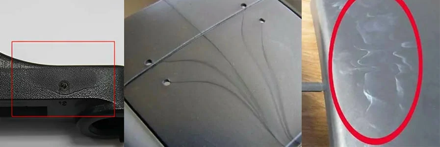
Injection Molding Defect: Ejector Pin Mark
Ejector pin marks typically occur when excessive force is applied by ejector pins during the ejection process, resulting in visible injection molding defects on the part surface. Effective measures to mitigate this issue involve optimizing both mold structure and molding processes to reduce ejector pin force and minimize the likelihood of ejector pin marks.
1. Mold Structure:
When the mold has a shallow draft angle or insufficiently polished ribs, it increases the resistance during part ejection. This, in turn, amplifies the force exerted by ejector pins on the part, leading to ejector pin marks or protrusions. To address this:
- Improve the polishing of ribs or increase the draft angle of the part to facilitate smoother ejection.
2. Molding Process:
Excessive packing pressure or prolonged packing time can cause over-packing of the part. This results in a higher mold-clamping force on the part, which increases the force exerted by ejector pins during ejection, potentially causing ejector pin marks or protrusions. To mitigate this:
- Reduce the packing pressure or shorten the packing time to prevent over-packing of the part.
Related resources: 15 Common Types of Injection Molding Defects, Causes, Remedies
By implementing these improvements in mold structure and molding processes, manufacturers can effectively reduce ejector pin marks, ensuring higher-quality molded parts with minimized surface defects and improved overall production efficiency.
Conclusion
Ejector pins are vital components in the injection molding process, ensuring efficient and damage-free ejection of molded parts. The choice of ejector pin type and material depends on the specific requirements of the molding process, including part geometry, material, and production volume.
At BOYI, we specialize in providing comprehensive injection molding solutions that leverage the latest technologies and best practices to optimize production processes.
Let’s Start A New Project Today
FAQ
Ejector pins are essential for the injection molding process as they are responsible for ejecting the solidified plastic part from the mold cavity once the molding cycle is complete. They ensure smooth and efficient removal of the part, allowing for continuous production.
Ejector pins are typically made from hardened tool steels such as H13, D2, A2, and M2. The choice of material depends on factors such as the expected production volume, mold complexity, and the type of plastic being molded. These materials offer varying degrees of hardness, toughness, wear resistance, and heat resistance to meet specific operational requirements.
Catalog: Injection Molding Guide

This article was written by engineers from the BOYI team. Fuquan Chen is a professional engineer and technical expert with 20 years of experience in rapid prototyping, mold manufacturing, and plastic injection molding.